
Positive displacement Blowers (lobe, Roots, screw) for pneumatic conveying : an Engineering Guide
Question or remark ? Please contact us at admin@powderprocess.net| Section summary |
|---|
| 1. What is a blower used for ? |
| 2. Design of rotary lobes blowers |
| 3. Performances of rotary blowers in pneumatic conveying applications |
| 4. Technical Sizing & Temperature Calculator |
| 5. Important design considerations & Equations |
| 6. Other designs of blowers |
| 7. Manufacturers of air blowers |
1. What is a blower used for ?
Positive displacement blowers applications
Blowers constitute the air movers in many pneumatic conveying systems running lean phase. They can be placed at the beginning of the pipe, delivering an overpressure, or at the end of the line to produce a vacuum. The most common type of air mover used for this purpose is the Roots blower, a volumetric blower that can be operated either in pressure or vacuum without specific changes.
2. Design of rotary lobes blowers
How does a Roots Blower work ?
Rotary lobe blowers are equipped with 2 rotors. By rotating and interlocking with each other, the rotors transfer a pocket of air from the suction side to the discharge side. Such a blower is often called a "Roots blower". Roots are positive displacement blowers. Standard designs have only 2 lobes (as shown below), while more modern designs utilize 3 lobes, which minimizes pulsations and yields better volumetric efficiency.
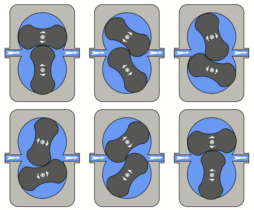

Considering the tight clearances between the housing and the rotors, the air handled must be particularly clean. It cannot accept any coarse dust, as foreign particles could lead to catastrophic failure or seizure of the lobes. In order to avoid dust entering the blower, systems are always equipped with a high-efficiency inlet filter at the suction.
For hygienic applications (such as food, dairy, or pharmaceuticals), oil-free air delivery systems must be specified to prevent compressed air contamination.
3. Performances of rotary blowers in pneumatic conveying applications
Which pressure can reach a Roots blower ?
Rotary lobe blowers can reach a maximum of 1.0 bar g (14.5 psig) in pressure and down to -0.5 bar g (-15 inHg) in vacuum applications. Maximum design operating pressures of pneumatic conveying blowers are therefore often set at conservative limits of 0.7 to 0.8 bar g in pressure, and -0.3 to -0.4 bar g under vacuum. One must also consider that compression heats up the air, which can be of critical concern for pressure dilute phase conveying of temperature-sensitive materials, often requiring the addition of an aftercooler. The performance of a blower is given on blower performance curves.
⚙️ Positive Displacement Blower Sizing & Temperature Calculator
Calculation Outputs:
| Actual Inlet Volumetric Flow (\(Q_1\)): | - |
| Total Absolute Pressure Ratio (\(r = P_2/P_1\)): | - |
| Thermodynamic Shaft Power Required (\(P_{shaft}\)): | - |
| Discharge Air Temperature (\(T_2\)): | - |
5. Important design considerations & Mathematical Equations
Thermodynamic Sizing of a Pneumatic Conveying Air Mover
Rotary lobe blowers are volumetric air movers, meaning they transfer a fixed, geometric volume of air per rotation. Therefore, when the system operates at pressure, any increase in pipe flow resistance (from line loading or blockage) causes the discharge pressure to increase. Because of slip and leakage back across the rotor clearances, the actual intake flow rate $Q_1$ will slightly drop as pressure rises. This can lead to a lower conveying gas speed in the pipeline.
Mechanical design engineers must ensure that even at maximum operating pressure drop, the air velocity remains securely above the saltation velocity or choking velocity to prevent systemic line blockages.
Key Blower Design Calculations:
The actual inlet air volume flow rate $Q_1$ is computed relative to the reference standard conditions:
\[Q_1 = Q_0 \cdot \left(\frac{P_{std}}{P_1}\right) \cdot \left(\frac{T_1}{T_{std}}\right)\]Where:
- \(Q_0\) is standard flow rate (\(Nm^3/h\) or \(SCFM\)).
- \(P_{std}\) is standard pressure (101.325 kPa abs or 14.696 psia).
- \(T_{std}\) is standard temperature (273.15 K or 519.67 R).
- \(P_1\) and \(T_1\) are absolute intake pressure and temperature.
The isentropic discharge temperature (\(T_2\)) resulting from adiabatic compression work is calculated as:
\[T_2 = T_1 \cdot \left[ 1 + \frac{1}{\eta_{ad}} \left( \left(\frac{P_2}{P_1}\right)^{\frac{k-1}{k}} - 1 \right) \right]\]Where:
- \(k\) is the adiabatic index of gas (1.4 for dry air).
- \(\eta_{ad}\) is the blower adiabatic efficiency.
The total theoretical shaft power requirement (\(P_{shaft}\)) is expressed via the work of compression:
\[P_{shaft} = \frac{k}{k-1} \cdot \frac{P_1 \cdot Q_1}{\eta_{ad} \cdot \eta_{mech}} \left[ \left(\frac{P_2}{P_1}\right)^{\frac{k-1}{k}} - 1 \right]\]💡 Plant Engineering Rules of Thumb:
- Pressure Limitation: Do not exceed a design pressure of 1.0 bar g (14.5 psig) with single-stage lobe Roots blowers to avoid excessive rotor thermal expansion and potential locking.
- Temperature Risk: Keep the calculated discharge temperature \(T_2\) below 120 °C (248 °F) for temperature-sensitive powders (such as sugar, chemical polymers, or dairy powders) or integrate a downstream Aftercooler.
- Sizing Margin: Always size the motor with a power surplus of at least 15% to 20% above calculated thermodynamic shaft power to handle dense-phase slugs or initial start-up torque surges.
- Filter Maintenance: Maintain pressure drop across inlet filters below 50 mbar (0.7 psi) to minimize intake throttling and maximize volumetric output efficiency.
6. Other designs of blowers
How many types of blower are there ?
The energy efficiency of the blower technology chosen is another primary criterion of system design. Hybrid or rotary screw blowers can achieve energy savings yielding an investment payback of under 2 years compared to classic Roots-type blowers when operated intensively.
What are the different kinds of blowers used in pneumatic conveying and their characteristics?
| Blower Type | Description | Applications and Advantages |
| Rotary Lobe Blowers | - Use rotating lobes to trap and move a fixed volume of air. | - Ideal for low-pressure applications in pneumatic conveying systems. |
| - Known for durability and reliability. | - Kaeser’s OMEGA series blowers with three-lobe rotors are popular. | |
| Centrifugal Fans | - Also known as centrifugal blowers. | - Provide high airflow at relatively low pressures. |
| - Commonly used in dilute-phase conveying systems. | - Efficient for supplying conveying air to the system. | |
| Roots Blowers | - Trap air in a fixed volume and discharge it against system pressure. | - Suitable for pneumatic conveying due to various advantages. |
| - Used in both positive and negative conveying systems. | ||
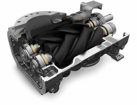
| Screw Blowers | - Deliver efficient and reliable low-pressure air via helical rotors. | - Used for conveying, aeration, and continuous process applications. |
| - Easy to maintain and deliver clean oil-free air. | - Often included in pre-engineered blower packages. |
| Feature | Rotary Lobe Blowers (Roots) | Screw Blowers | Side channel Blowers |
| Picture | 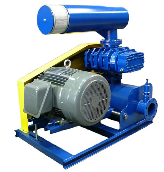 |
 |
 |
| Operating Principle | Positive displacement | Positive displacement | Dynamic displacement |
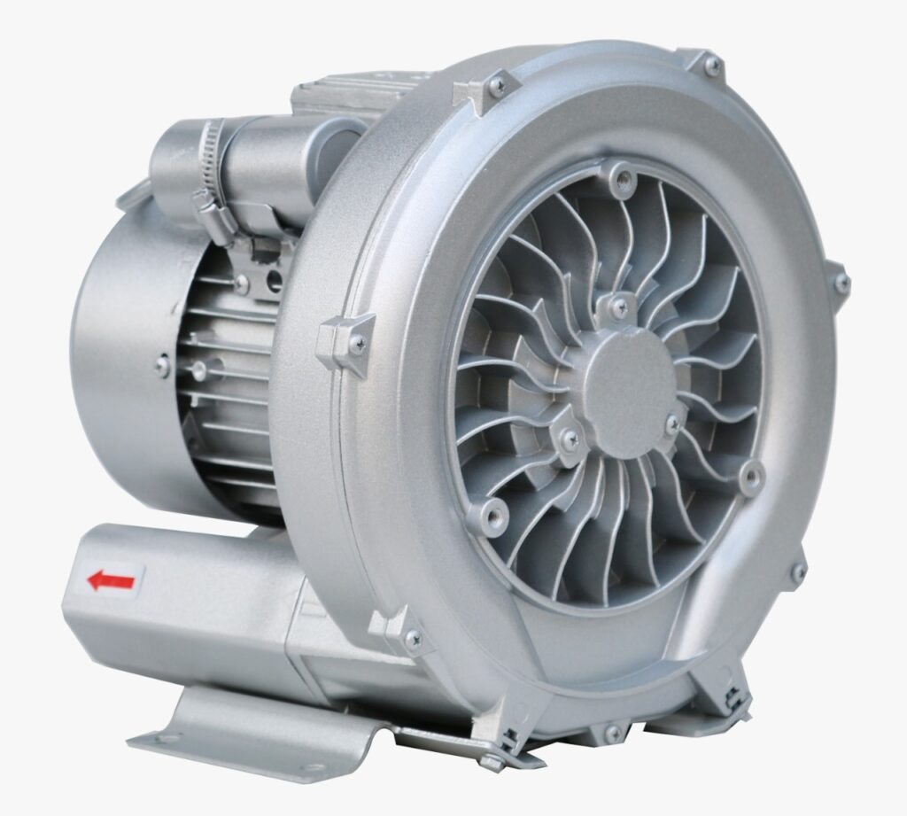
| Design | Two-lobed or three-lobed | Screw rotor | Impeller with side channels |
| Efficiency | Moderate | High | Moderate to High |
| Pressure Range | Up to 1 bar g | Up to 1.2 bar g | Up to 1.5 bar g |
| Vacuum Capability | Up to -0.5 bar g | Up to -0.6 bar g | Up to -0.7 bar g |
| Maintenance | Regular lubrication, filter replacement | Regular lubrication, filter replacement | Infrequent maintenance |
| Energy Efficiency | Moderate to High | High | Moderate to High |
| Noise Level | Moderate (Requires Silencer) | Low | Moderate |
| Application Flexibility | Suitable for lean phase conveying | Suitable for lean and dense phase | Suitable for low pressure applications |
| Environmental Consideration | Oil-free options available | Oil-free options standard | Oil-free options standard |
7. Manufacturers of air blowers
Positive displacement blower manufacturers
In order to get technical sizing documents or quotes of air blowers for your pneumatic conveying system, please contact the following engineering suppliers:
- Aerzen Compressors
- Robuschi Compressors
- Mapro Blowers (specializing also in side channel blowers)
(Note that PowderProcess.net has no financial ties or affiliation with the listed manufacturing companies)